7 Pin Trailer Wiring Diagram Black Wire
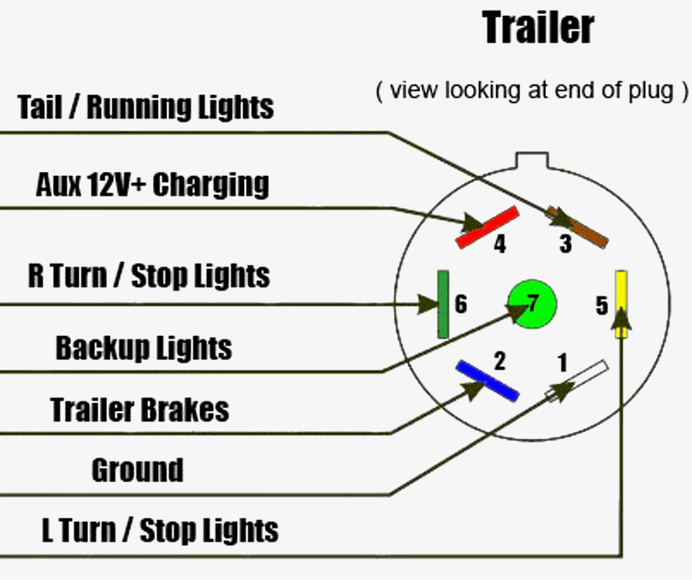
Below is a diagram for the original plug and socket showing the functions of each pin. The first diagram is a simple set up of two brake lights.
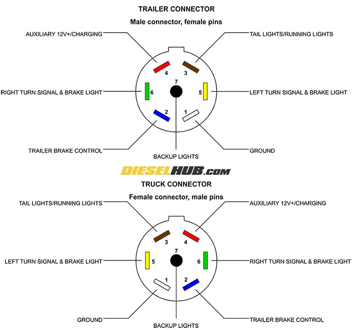
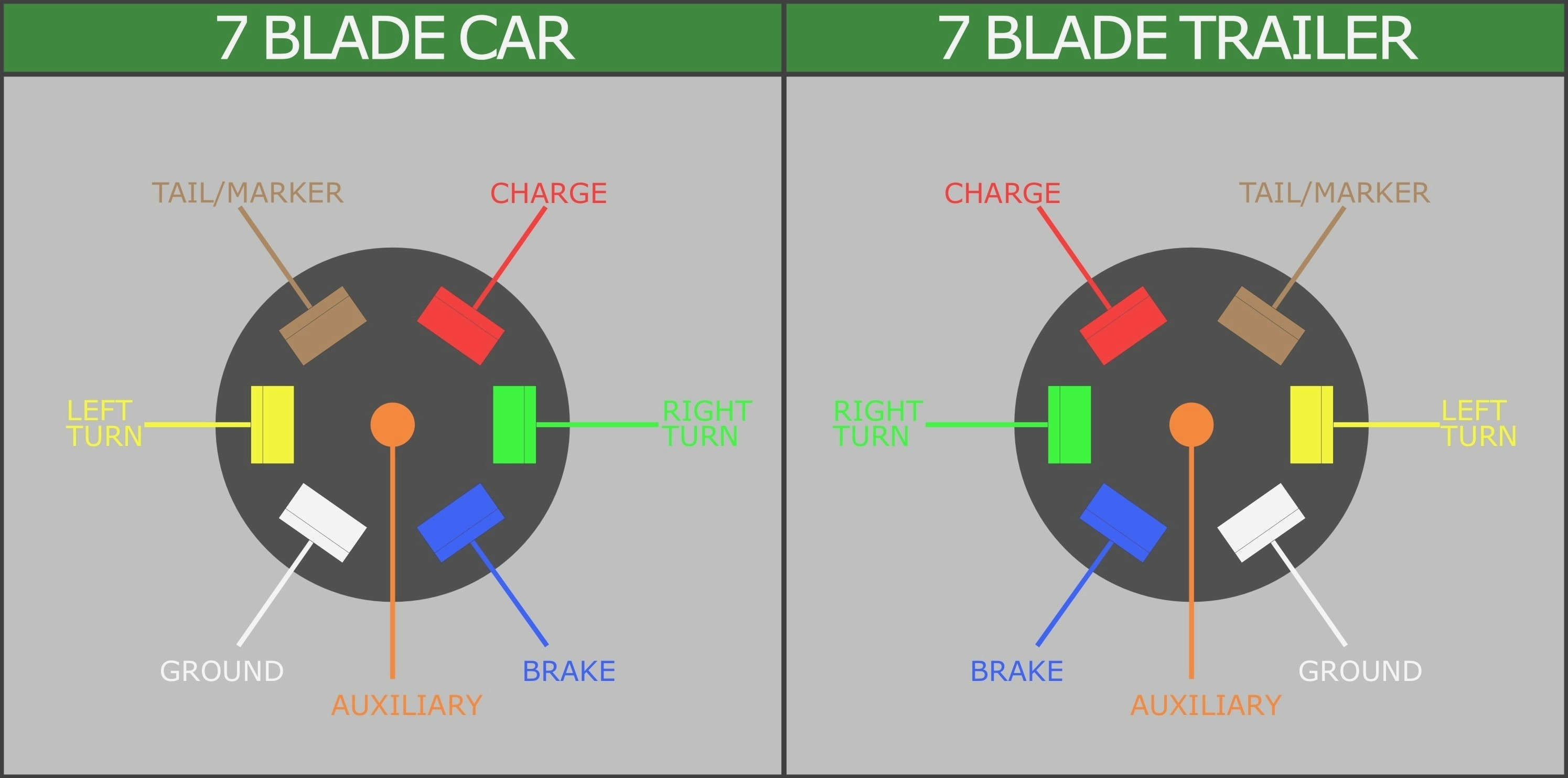
Trailer Connector Pinout Diagrams 4, 6, & 7 Pin Connectors
11/10 for 2011 wiring diagrams note:

7 pin trailer wiring diagram black wire. Be sure to check out our trailer tips on how to wire a trailer and troubleshooting trailer lights. The 7 pin flat plug will fit into a 12 pin flat socket and work perfectly. 7 pin trailer wiring diagram the 7 pin n type plug and socket is still the most common connector for towing.
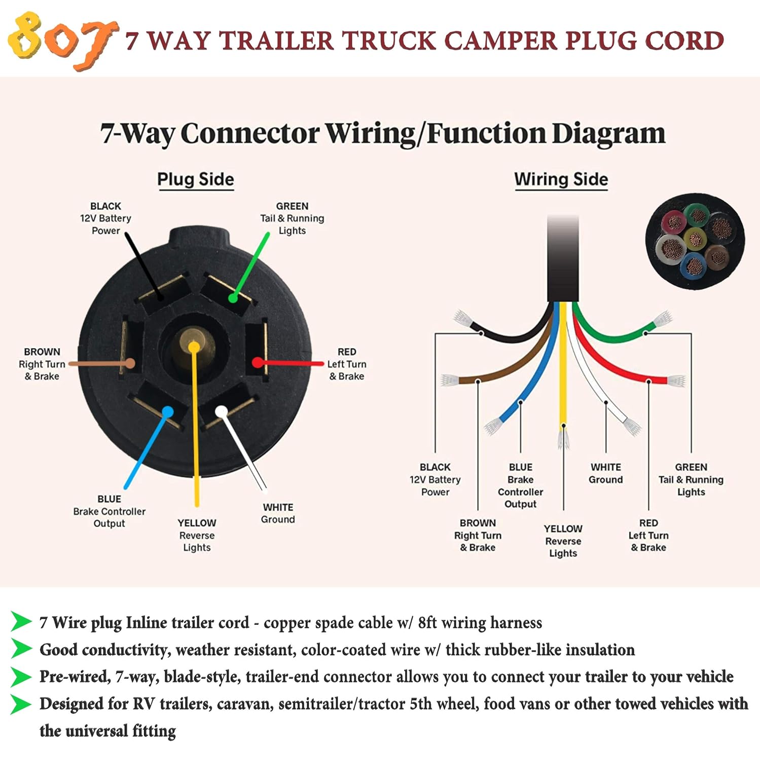
Blue = electric brakes or hydraulic reverse disable (see blue wire notes below.) in the trailer wiring diagram and connector application chart below, use the first 5 pins, and ignore the rest. A wiring diagram is a streamlined conventional photographic depiction of an electrical circuit. Click on the image below to enlarge it.
12 pin flat this is an extension of the 7 pin flat. If your truck has a built in 7 pin socket but you only need 5 of the pins. If not the arrangement won t work as it should be.
Australian trailer plug and socket wiring diagrams; Look at the wiring diagram for your truck's ignition switch. Here are two wiring diagrams for the 7 pin ‘n’ type trailer electrical plug.
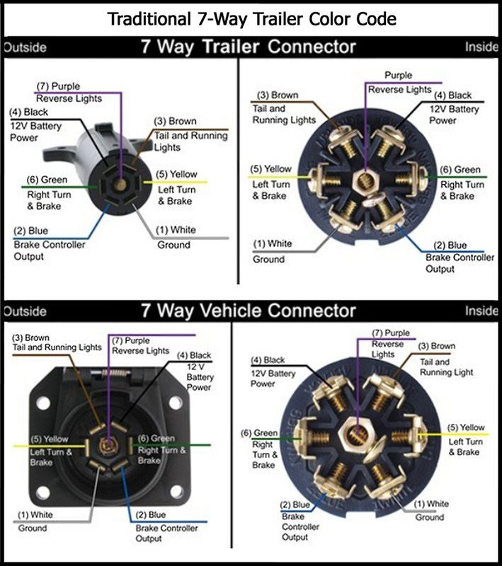
Australian trailer plug and socket wiring diagrams. 7 way plug wiring diagram standard wiring* post purpose wire color tm park light green (+) battery feed black rt right turn/brake light brown lt left turn/brake light red s trailer electric brakes blue gd ground white a accessory yellow this is the most common (standard) wiring scheme for rv plugs and the one used by major auto manufacturers today. The second diagram shows two brake lights, two indicators, two side lights and a fog light.
7 pin flat the best! Wiring diagram for chevy trailer plug new dodge caravan wiring. All diagrams are as viewed from the cable side.
There will be primary lines which are represented by l1, l2, l3, and so on. Trailer wiring diagrams trailer wiring connectors various connectors are available from four to seven pins that allow for the transfer of power for the lighting as well as auxiliary functions such as an electric trailer brake controller, backup lights, or. The above specification complies with british standard bs au 149a 12n and the.
The safety and security of all persons on or off the roadway, as well as those running a motorized vehicle, depends upon. The other colors remain the same for the other wires and their functionality as well. Connect to the brake controller and route the black and blue wires.
Click on the image below to enlarge it. 7 pin trailer wiring diagram black wire. The first diagram is a simple set up of two brake lights, two indicators and two side lights.
Below is an image of a trailer wiring diamgram that is very helpful to reference. Determine which color wire supplies constant power to the ignition switch. Each component should be set and connected with other parts in specific way.
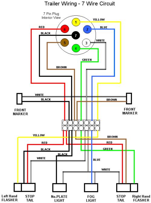
Locate this wire where it comes out of the interior fuse box. 7 pin 12n wiring diagram. 7 wire trailer connector wiring diagram.
The table and diagram below explains the connections used on a 7 pin setup. Make sure these have not inadvertently been swapped. As a professional rv transporter i have seen to many trucks wired with those 2 wires to small and cause a fire from overheating.
So i will have a 12v source to my trailer battery from the 7 pin and a converted 12v srouce from shore power via a charger. This supplies power to the road lighting of your trailer or caravan. This car is designed not only to travel 1 location.
All diagrams are as viewed from the cable side Injunction of two wires is usually indicated by black dot on the junction of 2 lines. If not, the arrangement won’t work as it should be.
Use this 7 pin trailer wiring diagram to properly wire your 7 pin trailer plug. Below we have the wiring diagrams for both a 7 and 13 pin connector. The safety and security of all persons on or off the road, as well as those operating a motorized vehicle,.
Use the 7 pin connector anyway see below and just leave out the last 2 wires. This vehicle is designed not only to travel 1 place to another but also to take heavy loads. If you are looking at the inside of the trailer connector where the wires mount to the terminals starting at.
If your vehicle is not equipped with a working trailer wiring harness, there are a number of different solutions to provide the perfect. In the trailer wiring diagram and connector application chart below use the first 5 pins and ignore the rest. As stated earlier, the lines in a 7 pin trailer wiring diagram with brakes signifies wires.
Sometimes, the cables will cross. The red color has been changed to orange and black to grey. But, it doesn’t mean link between the cables.
Australian 7 Pin Trailer Plug Wiring Diagram Wiring Corner

Reese 7 Pin Trailer Wiring Diagram Wiring Diagrams

7 Pin Round Trailer Connector Wiring Diagram Trailer

7Way Round Trailer Connector And Wiring
Wiring Diagram For 7 Pin Trailer Connector Trailer

7 Pin Rv Trailer Plug Wiring Diagram Trailer Wiring Diagram

7 pin wiring diagram Ford F150 Forum Community of Ford
Trailer Lights Wiring Diagram 7 Pin Australia Trailer

7, Plug Wiring Diagram Professional Trailer Connectors In

Trailer Plug 7 Pin Wiring Diagram Trailer Wiring Diagram

Trailer Wiring Diagram 7 Pin Round South Africa Trailer

7 Pin Socket Wiring / Pollak Black Plastic, 7Pole, RV

Dodge Trailer Wiring Diagram 7 Pin Wiring Diagram
Trailer Hitch Wiring Diagram 7 Pin Trailer Wiring Diagram

7 Pin Trailer Plug Wiring Diagram Database Wiring
Trailer Wiring Diagram 7 Pin Amazing 7 Wire Trailer
7 Way Round Pin Trailer Connector Wiring Diagram Database

7Pin connector in bed... DEAD? Ford Truck Enthusiasts
Ford 7 Pin Trailer Wiring Diagram Cadician's Blog