Rectifier Circuit Diagram Without Transformer
Half wave rectifier (without filter): The primary of the transformer is being connected to the ac supply mains.
How do capacitors smooth the output voltage of a rectifier
In order to use the 220v ac supply as 5v dc supply voltage step down transformer and a rectifier circuit are used which is shown in fig.
Rectifier circuit diagram without transformer. During the positive cycle of vs, point a is positive with respect to b causing diode d1 and d2 to forward bias and d3 and d4 to get reversed biased. The circuit is probably as per andy aka but from the photo, it does not have the r1 high voltage series r, the zener, the fuse and possibly not the c2 output cap (which may be with the battery). A tru is used to change ac to smooth dc.
It is transformer power supply circuit. 15v dc to 220v ac inverter circuit with mobile charger transformer. There is the insulation is between the primary and secondary.
Full wave rectifier using a bridge rectifier. A half wave rectifier circuit diagram looks like this: We use the transformer to reduce from high ac voltage to lower voltage.
In the circuit diagram, 4 diodes are arranged in the form of a bridge. A single diode is used in the hwr circuit for the transformation of ac to dc. The converter will not work with equipment incorporating a transformer at its input.
Initially, the capacitor is uncharged. About ac dc to without diagram circuit transformer converter. The circuit of hwr consists of following three main components −.
Many ways to increase current transformer of power supply current transformer electronic circuit projects electronics circuit. The circuit uses four diodes d1, d2, d3 and d4 connected in the form of bridge. These prices don’t sound like a lot, but this was the middle of the great depression.
Diodes with high piv rating are to be used. Circuit and working of converter. Full wave rectifier (without filter):
The capacitor charging continues until the input reaches its peak value (vp). This consists of a bridge circuit which includes four diodes. Ac to dc converter circuit diagram without transformer.
The name of the circuit in the given circuit is the ___. Ac to dc converter bridge rectifier connection diagram/how to make ac to dc converter@dae technical componentsdiodeswiresoldering iron This process can be attained through a transformer.
Output voltage is half of the full secondary voltage. Described converter is able without special transformer (and just plain air coil with inductance of about 30μh) to deliver an output voltage adjustable in range of 20v to. And a silver dollar then was worth about the same as a silver dollar today.
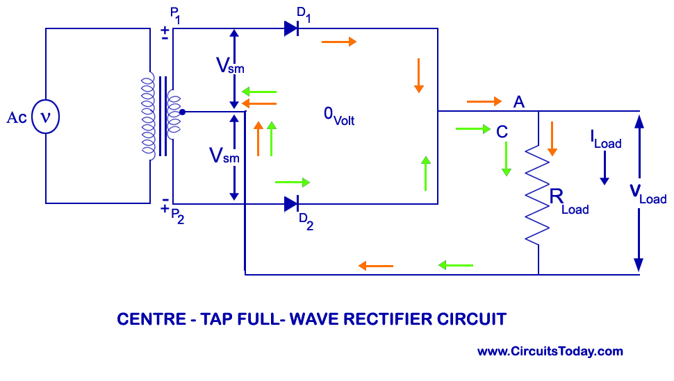
The diode is connected in series with the secondary of the transformer and the load resistance r l. Full wave rectifier circuit with and without filter electrical circuit diagram circuit diagram electronics circuit. The transformer secondary is connected to two diametrically opposite points of the bridge at points a & c.
These can be individual diodes, or it is also easy to obtain bridge rectifiers as a single electronic component. This results in the current to flow from a, through Bridge rectifier (using four diodes) if two branches of a circuit is connected by a third branch to form a loop, then the network is called a bridge circuit.out of these two the preferable type is bridge rectifier circuit using four diodes because the two diode type requires a center tapped transformer and not reliable when.
The name of the circuit in the given circuit is the ___. Also, we called half rectifier circuit. In the 1935 allied radio catalog , a “dry” rectifier has a catalog price of $3.73.
Third terminal at the secondary of the transformer is not connected. This tru device uses 240 vac & changes it into around 14 vdc for the battery charging. 1 shows the circuit of diode bridge rectifier.
Transformer rectifier unit circuit diagram. A diagram of the basic bridge rectifier circuit has a bridge rectifier block at the centre. Half wave rectifier (with filter):
A load(may be a resistance) Connect the circuit as shown in the circuit diagram. Half wave rectifier circuit diagram.
The circuit diagram of the transformer rectifier which is used within the battery charger of a car is shown below. Rectifier circuit is a converter, which converts ac supply in to dc supply. The load resistance r l is connected to bridge.
The circuit diagrams and waveforms we have given below will help you understand the operation of a bridge rectifier perfectly. Disadvantages of full wave rectifier: It is basic of unregulated supply circuit,12v 0.2a.
Working of a half wave rectifier. Connect the primary side of the transformer to ac mains and the secondary side to rectifier input.
Half Wave Rectifier(Explanation) YouTube

FULL WAVE RECTIFIER BY JAYASRI.K(221710303019)
Bridge Rectifier Circuit Design Details & Tips

220v Ac To 12v Dc Converter Circuit Diagram Without
[Solved] Build the fullwave bridge rectifier circuit
Bridge Rectifier without filter Multisim Live
Full Wave Rectifier Without Center Tapped Transformer
Full Wave Rectifier without Filter Multisim Live
Circuit Diagram Of Rectifier Circuit diagram, Circuit

Power Supply How It Works Circuit Diagram Images
Simple AC to DC converter using bridge rectifier
12v Ac To Dc Converter Circuit Diagram Without Transformer

☑ Half Wave Rectifier Circuit Using One Diode
Rectifier Circuit Diagram Half Wave, Full Wave, Bridge

Rectifier Circuit The final output of the rectifier in the

RECTIFIER_WITHOUT_DC_OFFSET Basic_Circuit Circuit

12V DC Power Supply without Transformer Power Supply
Basic Electronics
StudyCornor 220v AC to 12v DC Supply without using of
